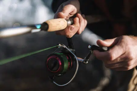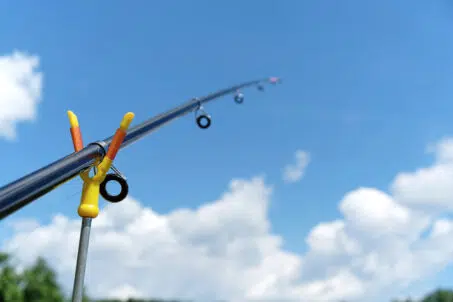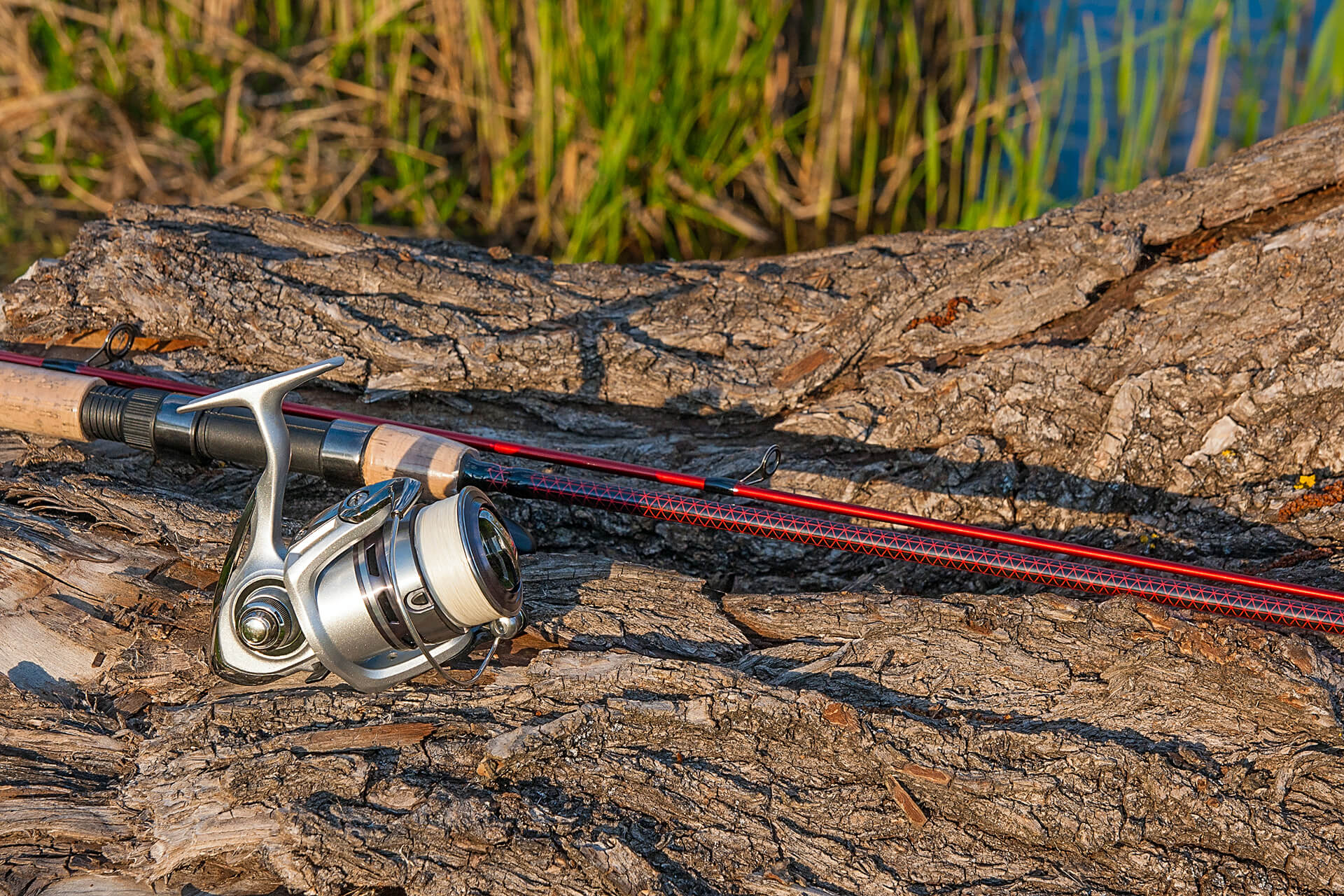
Before any guide is wrapped permanently, it should still be able to move. Temporary tape, an installed reel, a length of line, and a controlled load allow the builder to see whether the layout actually works before thread and finish make every position harder to change.
That temporary stage matters because guide spacing is not simply a matter of dividing a blank into attractive, evenly graduated intervals. The layout has to control line from the reel, follow the natural bend of the blank, and prevent sharp line angles or unwanted contact as the rod moves from a light load into a deeper fighting bend.
A guide spacing chart can provide a useful starting pattern, but it cannot account for every reel, blank action, handle position, guide family, line choice, or individual variation between blanks. Good spacing begins with a reference layout and ends with testing the actual rod being built.
Guide spacing has two different jobs
A guide train performs two related but distinct tasks. The guides closest to the reel manage how line enters the rod, while the running guides farther toward the tip control the line as the blank bends under load.
On a spinning rod, the reduction section has to manage coils leaving the spool and bring the line into a controlled path. The running guides then carry that path along the upper section of the blank. On a casting rod, line leaves the reel in a much straighter path, so the reduction problem is different even though the running guides still have to follow the loaded rod.
Treating the entire guide train as one evenly spaced sequence ignores those separate functions. Reduction-guide placement is shaped mainly by reel geometry and line flow. Running-guide placement is shaped more heavily by blank deflection and the way load moves through the rod.
A guide spacing chart is a starting layout
Guide spacing charts are useful because they give builders an organized place to begin. They can suggest guide count, establish approximate positions, and reduce the amount of trial and error needed before testing starts.
The problem begins when a chart is treated as the final answer.
Two blanks with the same length and listed action can still bend differently. Reel-seat placement changes the distance between the reel and the first guide. A different reel can alter spool height, diameter, and line path. Changing from one guide family to another can introduce different frame heights, ring sizes, or foot lengths.
A rod guide spacing chart should therefore be read as a set of temporary coordinates. Tape the guides in those positions, install the intended reel and line, then check how the layout behaves. The final guide locations should be accepted because the rod supports them under load, not because they match a printed set of measurements.
Complete the fixed parts before spacing the guides
Several parts of the build should be settled before guide placement begins. The reel seat, handle, intended reel, and tip top establish reference points that affect the rest of the layout.
Moving the reel seat changes the distance from the spool to the reduction train. Changing the reel can alter the height and direction of the line leaving the spool. A different tip top can change the ring height and the way the first running guide relates to the end of the blank.
The builder should also know which guide system will be used before final spacing. Replacing a tall reduction guide with a lower frame after the layout has been tested can change the line path enough to require another placement check.
Completing these decisions first prevents the spacing process from being built around parts that may later move.
Spinning rods begin with line control
Line leaves a spinning reel in expanding coils. The first guides have to control those coils and direct the line toward the smaller running guides farther along the blank.
This is why spinning-rod guide placement begins with the reel rather than with the tip. Spool diameter, spool position, reel height, line type, and the selected guide system all influence the reduction layout. The choke or transition into the running section also has to occur in a position that works with the complete system.
Once the reduction train has been established, the remaining distance between the final reduction guide and the tip section can be used to create an initial running-guide arrangement. Those guides are then adjusted through load testing rather than left in equal intervals simply because the gaps look orderly.
The current Anglers Resource guide spacing calculator is designed specifically for spinning rods and uses Fuji New Guide Concept and KR Concept layout logic. It supports specified spinning-rod lengths and Fuji guide configurations, so it should be used within those stated limits rather than treated as a universal calculator for every rod type.
Casting rods follow a different line path
A casting reel sends line toward the guides in a more direct path. The stripper and running guides generally sit closer to the blank than the reduction guides used on many spinning layouts, and there is no equivalent need to control large coils coming from a fixed spool.
That difference means a spinning guide spacing calculator should not be applied to a baitcasting build. Casting layouts need to be planned around the reel position, guide height, blank bend, and the path the line follows under load.
During a static test, the line should remain away from the blank or only approach it within the limits appropriate to the setup. Sharp line angles, heavy blank contact, or long unsupported sections of bend indicate that guide positions or guide count may need to change.
The basic principle remains the same for both rod types. The line should follow the working shape of the rod without fighting against it. The method used to reach that result differs because the line leaves spinning and casting reels differently.
Static load testing lets the blank show its bend
Static load testing is the most useful check for running-guide placement because it uses the actual blank rather than relying only on measurements.
The guides are first taped into temporary positions. The finished handle, reel, line, and tip top should already be in place, along with the reduction or stripper guides. The rod is then supported and loaded in a controlled manner so the tip reaches a deep working bend.
The Anglers Resource Static Load Tutorial uses a 90-degree relationship between the tip and handle as the central reference. The load is applied through a separate cord attached at the tip, while the fishing line is run through the guides under enough tension to show the line path. This allows the blank to take its natural curve instead of forcing the bend through the guide train itself.
With the rod loaded, the builder works from the tip section back toward the stronger part of the blank. Each running guide can be moved until the line follows the curve without severe changes in angle, excessive distance from the blank, or unwanted contact.
Watch the line rather than the gaps
A finished guide layout may not look perfectly even when the rod is unloaded. That is not necessarily a problem.
What matters is how the line behaves when the blank bends. The line should move through a controlled series of angles rather than making one or two abrupt turns. Flexible sections should not be left with long unsupported spans, while stiffer areas do not need guides added only to preserve a visual spacing pattern.
This is why static-tested layouts can appear unconventional on the bench. The blank may require guides to sit closer together in one area and farther apart in another. The spacing is responding to changes in stiffness along the rod rather than to a ruler-based progression.
The loaded rod provides the clearest evidence. If the line follows the bend smoothly and the guide train remains stable through different degrees of load, the layout is doing its job.
Flexible sections often need closer support
The upper and mid sections of a blank usually move through more deflection than the lower, stiffer sections. As the bend becomes deeper, line angles can become sharper if too few guides are carrying the load.
Adding a guide in a highly flexible area can reduce the angle between neighboring guides and keep the line path closer to the blank’s natural curve. The stronger butt section may need wider spacing because it bends less dramatically.
This does not mean that adding more guides is always better. Each guide adds weight, thread, finish, and another fixed point on the blank. The goal is to use enough guides to support the loaded rod without adding components that do not improve the line path.
Smaller and lower guides may allow a layout to use additional contact points with less weight than a traditional arrangement, but ring size still has to accommodate the line, knots, leaders, and fishing conditions expected in use.
Each stage needs a different final check
| Layout Area | Useful Starting Reference | What Confirms the Final Position |
| Reel and handle | Planned fishing application and angler fit | Reel and seat remain in their finished locations during testing |
| Reduction guides on a spinning rod | Reel geometry and the selected Fuji layout system | Line coils reduce into a controlled path toward the running guides |
| Stripper guide on a casting rod | Reel position, frame height, and blank type | Line enters the guide train cleanly and stays controlled under load |
| Running guides | Guide spacing chart or temporary equal spacing | Static testing shows a smooth line path that follows blank deflection |
| Guide count | Recommended layout for the rod type | Flexible sections are supported without unnecessary component weight |
| Tip section | Tip-top height and initial running-guide position | Line transitions smoothly through the deepest part of the bend |
The table provides a practical order of work, but none of the rows replaces testing. Each decision becomes final only after it has been checked on the actual assembly.
Guide height and ring size can change the spacing
Guide position cannot be separated completely from guide design. A tall frame changes the line path differently from a low running guide. A larger ring may require a different transition than a compact ring in the same general location.
This is especially important when builders switch guide families after beginning the layout. A spacing pattern developed with one set of frame heights may no longer work cleanly after different guides are substituted.
Ring size also has to reflect what will pass through the guide train. Knots, leader connections, line diameter, floating grass, ice, and other fishing conditions may require more clearance than a minimal layout provides.
The smallest practical guide is the one that performs the required job without creating an avoidable restriction. It should not be chosen from weight alone.
Test with the reel and line the rod will use
Guide spacing should be checked with the intended reel whenever possible. This is particularly important on spinning rods because changes in spool size and reel position can alter the reduction path.
The line and leader system also matter. A layout that works cleanly with thin braid and a compact knot may behave differently with heavier monofilament or a larger leader connection. The builder should test the setup that represents actual fishing use rather than the easiest line available at the bench.
A custom rod is being built for a specific combination of components and expectations. Testing with that combination is more useful than confirming that the spacing works under conditions the rod may never see.
Common spacing mistakes usually begin too early
One common mistake is wrapping guides permanently as soon as the chart measurements have been transferred to the blank. The builder loses the ability to make easy corrections before seeing the rod under load.
Another is forcing the spaces to look evenly graduated. Visual order can be appealing, but the blank may not bend in a mathematically even pattern. Moving a guide solely to improve appearance can create a worse line angle when the rod is loaded.
Applying spinning-rod measurements to a casting build is another avoidable problem. The two reel types produce different line paths, and their guide layouts should be developed accordingly.
Changing the reel, guide family, ring size, or handle position after spacing has been completed can also invalidate earlier work. Any meaningful component change should be followed by another line-path and static-load check.
Calculators and static testing work together
A calculator can save time by producing a reasoned starting layout. Static testing answers the next question by showing how that layout interacts with the individual blank.
For supported spinning builds, the Anglers Resource guide spacing calculator helps establish Fuji NGC and KR Concept positions from reel and rod information. The Static Load Tutorial then provides a method for refining the running guides according to the blank’s bend. Used together, these tools reduce guesswork without pretending that every rod is identical.
Casting rods, unusual blanks, specialty applications, and builds outside the calculator’s supported range need a different starting method. Static testing remains useful because it evaluates the actual line path and load distribution rather than relying on a generic sequence.
Approved trade accounts and custom builders can also access Fuji guides, tip tops, guide sets, and technical support through Anglers Resource when planning complete guide systems.
Good spacing becomes obvious under load
A guide layout should not be judged only while the rod is straight on a bench. It should be judged while the blank is doing the work it was designed to do.
Charts provide the first positions. Reel geometry establishes the reduction path. Static load testing shows where the running guides belong. The final arrangement may not be perfectly uniform, but it should allow the line to follow the rod through a controlled bend without severe angles or poorly supported sections.
That is the basic discipline behind custom fishing rod guide spacing. Start with a reliable system, keep every guide temporary until the rod has been tested, and let the loaded blank determine the final details.